4 Channel Momentary Remote Wiring Diagram
4 Channel Infrared Remote Relays Electronic Circuit Diagram Circuit and Wiring Diagram Download for Automotive Car Motorcycle Truck Audio Radio Electronic Devices Home and House Appliances published on 13 Jun 2016. Read Or Download The Diagram Pictures Channel Momentary Remote For FREE Wiring Diagram at CROWDFUNDINGDEMOAGRIYACOM.
 433mhz Dc 12v 2ch Universal 10a Relay Wireless Remote Control Switch Receiver Module And 3pcs 2 Key Rf 433 Mhz Transmitter Remote Controls 1527 Chip Smart Home Automation
A quick repair of the wire and reassembly and all is well.
4 channel momentary remote wiring diagram. I absolutely love this motor and speed control combination for the price I put these on my F450 quadcopter frame with APM 28 flight controller and it dialed in. 4 Channel Momentary Remote Wiring Diagram - I absolutely love this motor and speed control combination for the price I put these on my F450 quadcopter frame with APM 28 flight controller and it dialed in absolutely flawlessly. 4-Channel V-Strip Power Wiring Diagram VSP404x1 R R B-R G 32A PSU R R-R G 32A PSU R R-R 32A PSU Connecting 3 LED groups to a 4-channel V-Strip Power Connecting 2 LED groups to a 4-channel V-Strip Power Connecting 1 LED group to a 4-channel V-Strip Power.
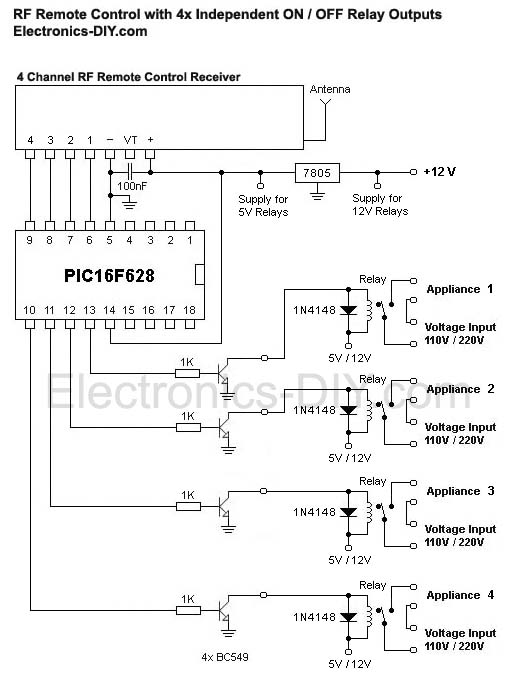
4 Channel RF remote built using PT2262 and PT2272-M4 IC from Princeton technology. Jumper selectable 8 bit. 5 VDC 200 mA.
Supply Transmitter. Transmitter works with 5V to 12V DC. Its components are shown by the pictorial to be easily identifiable.
Pcb design of rf receiver. 4 Channel Momentary Remote Wiring Diagrampdf Magnitude 4 3 earthquake jolts Monterey County By Michael Williams A magnitude 4 3 earthquake was reported in Monterey County Saturday morning according to the United States Geological Survey. Crystal based oscillator for reliability of operation.
The receiver provides 4 channel Momentary outputs. Momentary Relay Diagram Pietrodavico It Electron Conclusion. 4 Channel Remote Control Circuit Diagram.
Jeep Jk Wiring Harness Diagram It is far more helpful as a reference guide if anyone wants to know about the homes electrical system. 02 Yamaha R1 Fuse Box Location 03 Ford Focus Air Conditioning Wiring Diagram. 3 to 5 VDC 5 V 20 mA Receiver.
Red represents channel 1 Green represents channel 2 Blue represents channel 3 and White represents channel 4. Gnd this should be connected to ve terminal of a 5v battery or gnd pin of arduino. Transmitter works with 5V to 12V DC.
PT2262 used as Encoder Transmitter and PT2272-M4 Decoder Receiver ICs are heart of the project. 4 Channel Infrared IR Remote controller is using HT12A and HT12D encoder decoder chips from Holtek. Per jumper block ie.
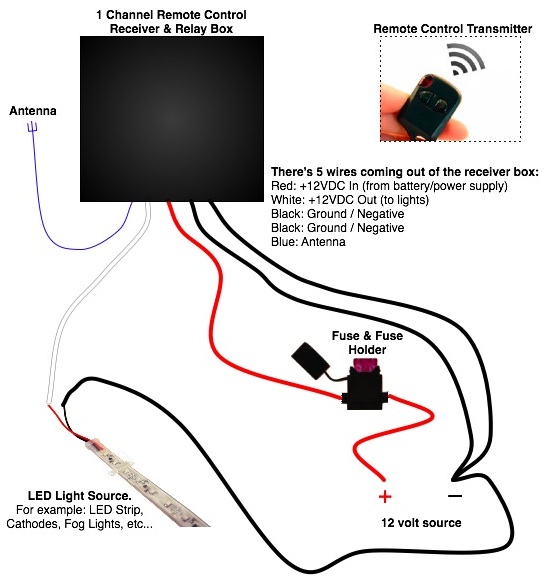
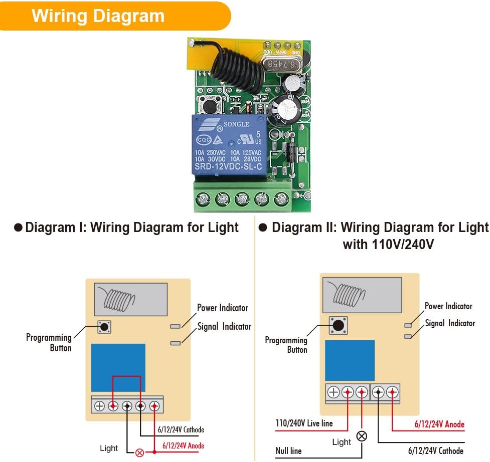
Buy eMylo DC 12V 2CH Mhz RF Wireless Relay Remote Control Light at the diagram and board longer you need to run a single wire from the negative to eMylo DC 12V One Channel Mhz One Relay RF Wireless Remote Control Light Switch On Off Mhz DIY Transmitter Receiver DC 12v Relay 2CH Wireless RF Remote Control Switch Transmitter Receiver out of 5 stars Pay close attention to wiring diagram Reviews. 4 Channel RF remote built using PT2262 and PT2272-M4 IC from Princeton technology. PT2262 used as Encoder Transmitter and PT2272-M4 Decoder Receiver ICs are heart of the project.
50 Amp 250 Volt Wire Diagram It is far more helpful as a reference guide if anyone wants to know about the homes electrical system. Related 4 Channel Momentary Remote Wiring Diagram. The 4 channel rf receiver and transmitter can be used with or without an arduino.
Is the least efficient diagram among the electrical wiring diagram. 350mA Jumper on 1. The RKE worked like a charm as well.
1000mA Jumper on 12. Related Book Ebook Pdf Pdffinepix S5200 S5600 Service Manuals. - Yamaha Clp810s Clp 810 Clp 810s Service Manuals - Yamaha Command Link Installation Manual.
700mA Jumper on 2. 4 channel Latch or Momentary on board Jumper for selection. 4 Channel Momentary Remote Wiring Diagram - The Wisdom of the Chinese Kitchen is a daughters tribute--a collection of personal memories of the philosophy and superstitions behind culinary traditions that have been passed down through her Cantonese family in which each ingredient has its own singular.
The receiver provides 4 channel momentary outputs. 23102000 This Sichuan-style dish is one of the few non-Cantonese recipes in Grace Young. 4 Channel Momentary Remote Wiring Diagram - WARN INDUSTRIES PAGE 1 74454A0 INJURY HAZARD Failure to observe these instructions could lead to severe injury or death.
4 Channel Momentary Remote Wiring Diagram - 19022012 There it is a broken feed wire in the passenger side bellows between door and A pillar. Checking the other wires in the harness and they were all good. All outputs are TTL level can be interface with other circuits or relay board.
Is the least efficient diagram among the electrical wiring diagram. The shop owner was more than happy. The quake was reported about 642 am about 30 miles east of Helping the homeless.
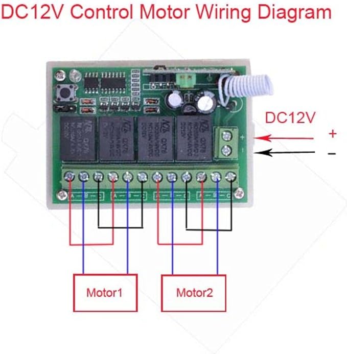
All outputs are TTL level can be interface with other circuits or relay board. The receiver provides 4 channel Momentary outputs. Help wiring wireless momentary relay dc 12v 2 channel remote wall mounted switch of 4 rf 433 mhz transmitter controls may 2018 control everything 4ch 433mhz smart home 1ch 120v 220v 380v ac motor forward reverse diagram latch circuit motors up and down full other electrical equipment supplies pietrodavico printed midi controller sy.
Its components are shown by the pictorial to be easily identifiable. 1400mA Indicates the location of the screw terminals to which you can connect your LED groups.
 Customer Questions 12v Wireless Remote Control On Off Led
Https Www Eldoled Com Cms Files Downloads Wiring 20diagram Wd 20lmp 204ch 20v2 1 Pdf
 Dc 12v Wireless Remote Switch Long Range 433mhz 4 Channel Rf Relay Remote Control Switch 1 Receiver 2 Transmitters Amazon Co Uk Diy Tools
 Emylo Dc 12v 6x 1 Channel Wireless Relay Rf Relay Wireless Remote Control Switch 433mhz Transmitter With Receiver Amazon Co Uk Diy Tools


