Eaton Shunt Trip Breaker Wiring Diagram With Push On
Its components are shown by the pictorial to be easily identifiable. Wiring a GFCI Circuit Breaker.
 Shunt Trip Wiring Diagram Single Speed Dual Cooling Fan Wiring Diagram Cts Lsa Tukune Jeanjaures37 Fr
Undervoltage release x Shunt release The main difference between a shunt trip and an undervoltage release is that the.
Eaton shunt trip breaker wiring diagram with push on. It shows the parts of the circuit as simplified forms and also the power and also signal connections between the tools. In industrial state Electric operator duty is to operate the machinery and his duty is on the front of Main panel board. Switches are tripped by a voltage pulse or by the application of uninterrupted voltage.
Trying to wire 2 square d shunt trip breakers to a vent hood and lights in vent hood. When the shunt release is live contact with the circuit-breakers main contacts on switching on is reliably prevented. A wiring diagram is a streamlined standard photographic representation of an electrical circuit.
Siemens shunt trip breaker wiring diagram Shunt Trip Circuit Breaker Wiring Diagram Saleexpert Me In Square Best Ideas D And. 1 Customer supplied NO. To Our Valued Customers.
Does Eaton have a switch-disconnector for photovoltaic applications. Installation of the shunt trip To install the shunt trip proceed with the following eight steps. In this post i am just tell you about wiring of single EPO button with shunt trip MCCB breaker.
3 Required voltage to be applied to lead coming out of shunt trip in order to trip the breaker. Wire-Cuts can take 1-2 business days to ship. Shunt trips accessories in QO breakers are factory installed only and can not be added to.
Shunt releases The shunt trip release is responsible to trip the circuit breaker when a voltage pulse or an. When replacing a shunt trip both the shunt trip and the cut-off switch must be replaced. Eaton Shunt Trip Breaker Wiring Diagram With Push On It is far more helpful as a reference guide if anyone wants to know about the homes electrical system.
As you know that Safety is important in electricity works. It shows the elements of the circuit as simplified shapes as well as the power as well as signal connections in between the gadgets. Shunt releases with push-in terminals.
The mounting is always flexible and easy thanks to the modular function groups. How to wire a residential shunt trip breaker. How to wire a shunt trip.
NZM Shunt release wiring diagram A Normally Open NO set of contacts such as a momentary push button must be supplied. Is the least efficient diagram among the electrical wiring diagram. Shunt trip and overcurrent trip switch warning 1only qualified electrical personnel should be permitted to work on the equipment.
A wiring diagram is a simplified standard photographic depiction of an electric circuit. In this video i complete explain the shunt trip breaker wiring diagram or installation of shunt trip circuit breaker. 2 Shunt trips can be factory added to 1 2 and 3 pole plug in breakers.
Remove the front cover by unscrewing the. 3drawout circuit breakers should be levered racked out to the disconnect position. NZM Shunt release wiring diagram A Normally Open NO set of contacts such as a momentary push button must be.
The shunt trip opens the circuit breaker when its coil is energized by a voltage input. Assortment of ge shunt trip breaker wiring diagram. 2always de-energize primary and secondary circuits if a circuit breaker cannot be removed to a safe work location.
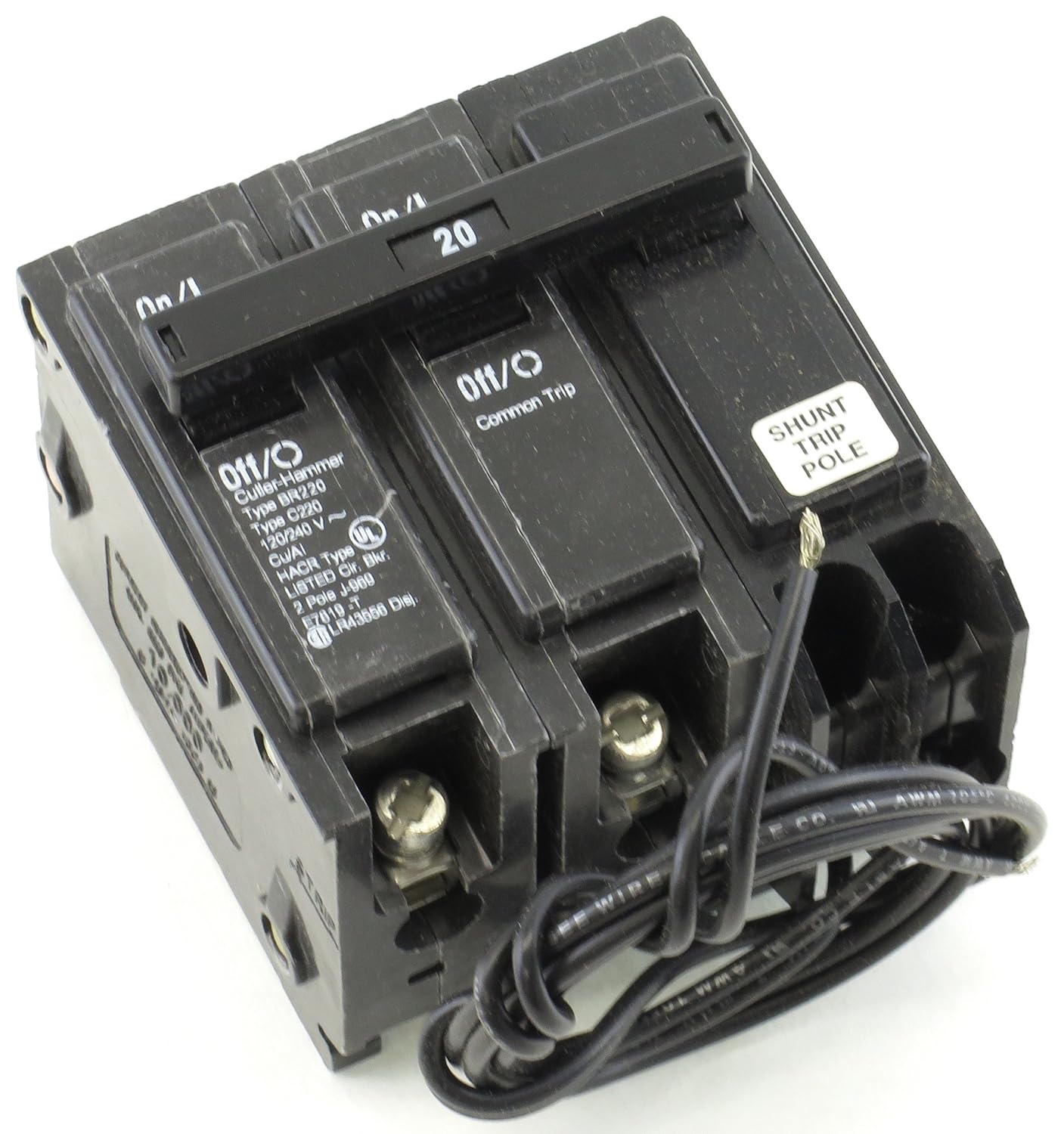
In this video i also shown with video. This 20 amp 120 volt breaker is a form of gfci that can be installed at the circuit source. Collection of square d shunt trip breaker wiring diagram.
Shunt Trip Breaker Wiring Diagram with EPO Button. Today i am writing about shunt trip breaker wiring diagram which related with safety and protection of electricity. You can replace the old Dig Trip of the breaker for the PXR one by maintaining the same cassette but you need also to.
As you know that electricity is dangerous but its become more dangerous when its upgrade from the 220 volts to 3 phase 440 volts. This diagram illustrates wiring for a circuit breaker with a built-in ground fault circuit interrupter or gfci. Eaton SNT3P11K Shunt Trip 110-240VAC 110-125VDC Mounting K-Frame Breaker Shunt Trip With Pigtail Leads 110-240 Volt AC or 110-125 Volt DC Left Right or Neutral-Pole Mounting For K-frame Breaker.
Tutorial for wiring a shunt trip QO and QOB Circuit Breaker. Normally Open momentary push button must be supplied. This kind of circuit is used for dishwashers whirlpool spas and other locations where water contact is likely.
1 breaker is 20 amp 120 volt other is 20 amp 240 volt hood was wired a while ago with new code changes need to.
Https Encrypted Tbn0 Gstatic Com Images Q Tbn And9gcq2zd88 P3p3 Zfbwiympgw5pm5ijgsiakd3yszvkgvw Bz3ofs Usqp Cau
 Madcomics 120v Shunt Trip Breaker Wiring Diagram
Https Encrypted Tbn0 Gstatic Com Images Q Tbn And9gcr9f7nrfcn7mf6nevzt2nkgzattiiczgp Rjk6 Wyo04uhnova9 Usqp Cau
Https Encrypted Tbn0 Gstatic Com Images Q Tbn And9gcrj0bxhdbx3ovusp2xh7nfd2pf0pbdk4syepi19x1gfmsnk5tpn Usqp Cau
 Dol Starter Diagram Direct Online Starter For 3 Phase Motor Electrical Circuit Diagram Diagram Electrical Wiring Diagram


